Antec Dark Fleet DF-30 User Manual
Browse online or download User Manual for Computer cases Antec Dark Fleet DF-30. Antec Dark Fleet DF-30 User manual
- Page / 30
- Table of contents
- BOOKMARKS
- THE ADVANCED 1
- GAMING FORCE 1
- DF-30 USER’S MANUAL 2
- TABLE OF CONTENTS 3
- NTRODUCTION 4
- ECTION 1 4
- GETTING TO KNOW YOUR CASE 5
- HARDWARE 9
- INSTALLATION 9
- SECTION 2 9
- ETTING UP 10
- OTHERBOARD INSTALLATION 12
- ABLE MANAGEMENT 15
- LOADING: 19
- UNLOADING: 19
- SECTION 3 22
- FRONT I/O 22
- Key (No Connection) 23
- COOLING 25
- SECTION 4 25
- INCLUDED FANS 26
- OP 140 MM TWOCOOL™ FAN 27
- RONT 120 MM BLUE LED FANS 27
- PTIONAL FANS 28
- ASHABLE AIR FILTERS 29
Summary of Contents
DF- 30 DARK FLEET THE ADVANCED GAMING FORCE U S E R M A N U A L
10 2.1 SETTING UP Put the case upright on a flat, stable surface so that the rear panel (power supply and expansion slots) is facing you. To remove
11 Now rest your case with the left side up. Here’s what we’ll be working with first: A – Power supply mounts B – 5.25” drive bay area C – 3.5” dr
12 2.2 MOTHERBOARD INSTALLATION Before proceeding: - Check the manual for your CPU cooler to find out if there are steps you must do befor
13 3. Now remove your motherboard by lifting it up. Lift your motherboard out to install the standoffs. 4. Install standoffs as needed and put th
14 Note: The DF-30 comes with a CPU cutout on the motherboard tray, which will allow you to change your CPU heatsink without removing the motherboar
15 Use these screws to secure your power supply to the case. 2.4 CABLE MANAGEMENT There is a cable management compartment behind the 3
16 2.5 INTERNAL 3.5” DEVICE INSTALLATION The DF-30 includes two Fleet-Release™ access doors. With the front bezel facing you, they are l
17 Installing a 3.5” internal device 3. Fasten the device in place with the provided screws on both side of the drive cage. Make sure to install s
18 2.6 EXTERNAL 3.5” DEVICE INSTALLATION There is one external 3.5” drive bay under the 5.25” drive bays. Remove this drive bay cover. 1. Caref
19 2.7 USING THE TOP 2.5” HOT-SWAP BAY The DF-30’s top 2.5” hard drive bay is hot-swap capable. To use the hot-swap feature, ensure that y
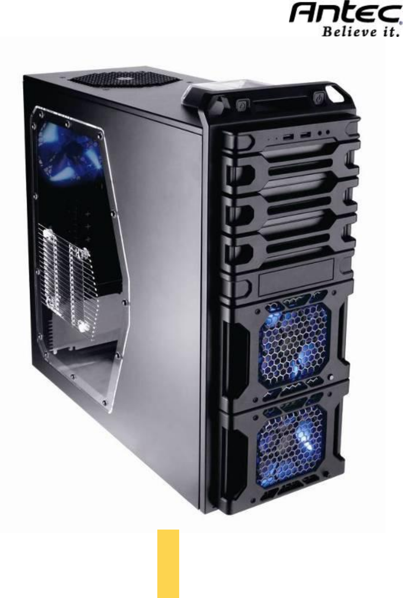
2 DF-30 USER’S MANUAL Congratulations on your purchase of the Antec Dark Fleet DF-30. Performance form meets industrial-grade function in the DF-30.
20 2.8 EXTERNAL 5.25” DEVICE INSTALLATION There are three externally accessible 5.25” drive bays. Before you begin, remove both side pa
21 2.9 INTERNAL 2. 5” DEVICE INSTALLATION There is a 2.5” device mounting location located at the bottom of the case. To use this mount
22 3. FRONT I/O PORTS SECTION 3
23 Pin Signal Names Pin Signal Names 1 USB Power 1 2 USB Power 2 3 Negative Signal 1 4 Negative Signal 2 5 Positive Signal 1 6 Positive Signal 2 7 Gro
24 3.3 POWER SWITCH / RESET SWITCH / HARD DISK DRIVE LED CONNECTORS Connected to your front panel are LED and switch leads for power, re
25 COOLING SYSTEM SECTION 4
26 4.1 INCLUDED FANS Standard fans on the DF-30: A – 1 x 120 mm rear TwoCool™ LED fan B – 1 x 140 mm top TwoCool™ fan C – 2 x Fleet-Re
27 4.2 TOP 140 MM TWOCOOL™ FAN The DF-30 comes with one 140mm TwoCool™ LED fan. This fan has a two-speed switch that lets you choose the
28 4.4 REAR EXHAUST 120 MM TWOCOOL™ FANS There is one 120 x 25 mm TwoCool™ blue LED fan preinstalled at the rear of the case. This fan is
29 4.6 WASHABLE AIR FILTERS There is a filter located behind the faceplate of each Fleet-ReleaseTM Access Doors. There are total of tw
3 TABLE OF CONTENTS SECTION 1: INTRODUCTION 1.1 Getting to know your case…………………………………………………. 5 1.2 Case specifications………………………………………………………….
30 Antec, Inc. 47900 Fremont Blvd. Fremont, CA 94538 tel: 510-770-1200 fax: 510-770-1288 Antec Europe B.V. Stuttgartstraat 12 3047 AS Rotterda
4 INTRODUCTION SECTION 1
5 1.1 GETTING TO KNOW YOUR CASE Drive bays Hardware mounts 1 5.25” drive bays 8 Motherboard stando
6 1.2 CASE SPECIFICATIONS CASE TYPE Mid Tower COLOR Matte black DIMENSIONS 19.1″ (H) x 7.8″ (W) x 19.1″ (D) 485 mm (H) x 198 mm (W) x
7 1.3 BEFORE YOU BEGIN In order to ensure that your building experience with the Dark Fleet DF-30 will be a positive one, please take no
8 1.4 LOCATING AND POSITIONING YOUR COMPUTER Your DF-30 has backwards- and top-facing exhaust fans, as well as front-mounted intake fans
9 HARDWARE INSTALLATION SECTION 2
Related products and manuals for Computer cases Antec Dark Fleet DF-30

 (10 pages)
 (23 pages)
 (5 pages)
© 2020, manymanuals.com. All rights reserved. | 1.272 s |
 Manymanuals.com
 Manymanuals.de
 Manymanuals.fr
 Manymanuals.it
 Manymanuals.pl
 Manymanuals.cz
 Manymanuals.es
 Manymanuals-pt.com
Comments to this Manuals